- A2L File - ASAM MCD-2 MC Description Language
- Real Time Example
- Protocol Layer and Transport Layers
- Measuring & Calibrating Throughout the Development Process
- Software Debugging over XCP
- What is CCP/XCP?
- History of CCP/XCP
- Master-Slave Architecture
- CCP/XCP Use Cases
- Major Changes in XCP vs. CCP
- CCP/XCP vs. UDS
- CCP Message Types
- CRM-DTO: Command Response Message
- DAQ-DTO: Data Acquisition Message
XCP Protocol
Giri velavan
Published: 9 months ago
Calibration
It means comparing the thing you’re calibrating to a known standard, then adjusting it, or drawing up an error
curve or chart, so you can translate a measurement to the actual value.
Calibration is the process of checking and adjusting a measuring instrument to ensure its accuracy. It involves
comparing the instrument's readings to a known standard or reference.
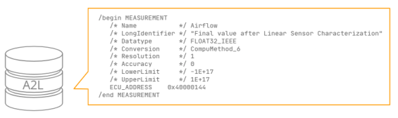
A2L File - ASAM MCD-2 MC Description Language
An A2L file is a structured ASCII text file that contains information about an ECU's (Electronic Control Unit)
measurement, calibration, and event definitions:
An A2L file is a standardized description file used in the automotive industry, particularly in ECU (Electronic
Control Unit) development. It is part of the ASAM MCD-2 MC standard and provides essential metadata to
configure and calibrate an ECU. Here's an overview:
What is an A2L File?
- Purpose: Contains information about the structure, memory layout, and calibration variables of the ECU.
- File Format: ASCII text file with a
.a2lextension. - Usage: Used with calibration tools like ETAS INCA, Vector CANape, or ATI Vision to access and modify
ECU parameters.
Real Time Example
Electric Vehicle (EV) Battery Management System (BMS)
Scenario: Monitoring and calibrating the BMS to ensure optimal battery health and safety.
Use of A2L:
- The A2L file provides variables like
Battery_Cell_TemperatureandCharge_Limit. - Real-time measurements help engineers calibrate thresholds for charging, discharging, and thermal management.
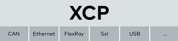
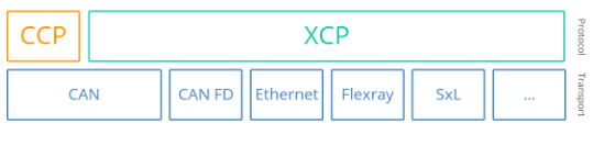
Protocol Layer and Transport Layers
The data transport takes place via different transport layers. The following transport layers are particularly
relevant in the automotive sector:
- XCP on CAN and CAN FD
- XCP on SxI (SPI, SCI)
- XCP on Ethernet (TCP/IP and UDP/IP)
- XCP on FlexRay
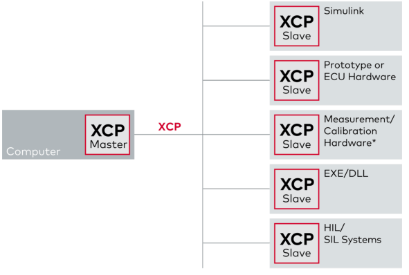
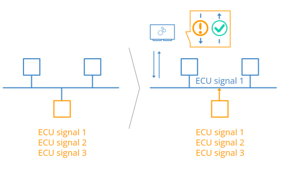
Measuring & Calibrating Throughout the Development Process
In measuring and calibrating with XCP, the specific environment in which the code or model (Simulink, rapid
prototyping hardware, HIL, SIL, etc.) is run is irrelevant. That is, in optimizing the control algorithms for the ECU,
you can use one and the same tool, always performing similar work steps. This makes configurations,
measurement data, and description files usable and interchangeable throughout the development process.
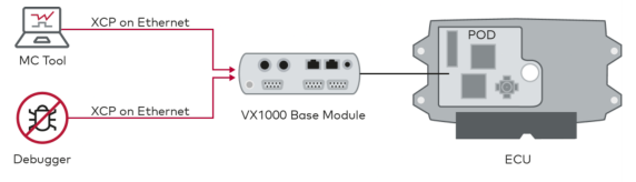
Software Debugging over XCP
XCP Protocol
In the ECU, the debugging interface (e.g., JTAG, DAP, ...) is used both for debugging the software and for
measuring and adjusting via XCP. By including the debugging use case in the XCP standard, you can use the
debugger and the measurement and calibration tool via the same robust physical interface. This also allows you
to debug ECUs that are already permanently installed in the vehicle.
The debugger software is connected via XCP on Ethernet to an XCP slave of the VX1000 hardware. The
VX1000 hardware offers several XCP slaves, which allow simultaneous use of debugging, measuring, and
adjusting. This maximizes the use of the ECU debugging interface and achieves optimal performance in all use
cases.
The PODs are connected to the ECU either via serial interfaces such as JTAG and DAP or via parallel data
trace interfaces such as Aurora and RTP/DMM. The debugger software and the MC tool are connected to the
VX1000 base module via XCP on Ethernet.
What is CCP/XCP?
The CAN Calibration Protocol (CCP) is an interface that enables read/write access to an Electronic Control Unit (ECU).
It allows calibration, data measurement, flashing, and more.
The Universal Measurement and Calibration Protocol (XCP) is the successor to CCP with various improvements,
including support for more transport layers such as Ethernet, FlexRay, and SxI.
The CCP/XCP protocols have extensive overlaps but also important differences. To avoid confusion, we will first
focus on covering the CCP protocol, then go through XCP on CAN, with explicit clarification on key differences.
Motivation for CCP/XCP
To understand why CCP/XCP is needed, let's revisit the CAN bus:
- CAN enables communication between different ECUs in a vehicle/machine.
- ECU inputs and outputs are broadcast on the CAN bus.
- However, the inner workings of an ECU remain a black box.
Here, CCP/XCP provides direct access to the ECU’s internal parameters, allowing:
- High-frequency parameter data requests, which may otherwise only be known to the ECU.
- Modification of ECU algorithms and variables, enabling easy testing and calibration.
Most importantly, CCP/XCP standardizes these interfaces across different ECU manufacturers.
History of CCP/XCP
The CAN Calibration Protocol (CCP) was originally developed by a calibration systems company, Helmut Kleinknecht.
Within a few years, it was improved by a working group, ASAP (Arbeitskreis zur Standardisierung von Applikationssystemen),
which included Audi, BMW, VW, and others. Later, ASAP was renamed to ASAM
(Association for Standardization of Automation and Measuring Systems).
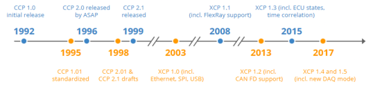
Key Milestones:
- 1992: CCP 1.0 initial release by Helmut Kleinknecht
- 1995: CCP 1.01 standardized by ASAP
- 1996: CCP 2.0 released by ASAP
- 1998: Drafts of CCP 2.01 and CCP 2.1 were prepared
- 1999: CCP 2.1 was released in February
- 2003: XCP 1.0 incl. support for CAN, Ethernet, SPI, USB
- 2008: XCP 1.1 incl. support for FlexRay
- 2013: XCP 1.2 incl. ECU description file updates + CAN FD
- 2015: XCP 1.3 incl. ECU states, bypass handling, time correlation
- 2017: XCP 1.4 incl. improvements and new DAQ mode
- 2017: XCP 1.5 incl. software debugging without a debug adapter
Today, XCP (aka ASAM MCD-1 XCP) is the successor to CCP (aka ASAM MCD-1 CCP). However, in practice,
many ECUs still use CCP, making it essential to understand both protocols and their key differences.
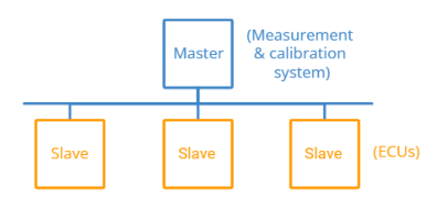
Master-Slave Architecture
The CCP/XCP protocol is based on a single-master/multi-slave concept.
- An external measurement & calibration tool (e.g., a PC, device, or data logger) serves as the master.
- The master can read/write from one or more ECUs (also called slaves).
Interface Layers
- The interface between the master and slave is called ASAP1 or ASAM MCD-1.
- The CCP/XCP standard also defines ASAP2 or ASAM MCD-2 MC, which specifies the interface between
the master and an ECU description file.
ECU Description Files (A2L)
- In practice, a database describes all relevant ECU information in a standardized file format called A2L
(ECU Description Files). - These files provide essential metadata to configure, measure, and calibrate ECUs efficiently.
CCP/XCP Use Cases
The CCP/XCP protocol enables multiple use cases:
- Plug & Play ECU Measurement and Calibration
- Recording of ECU Data at Microsecond Resolution
- Access to Data Internal to the ECU (not broadcast on CAN)
- Measurement via Polling or Based on Events (time, triggers)
- Real-Time Calibration/Adjustment of ECU Algorithm Variables
- Flash Programming of ECUs
- Optional Authentication for Secure Access
- Mainly for OEM Development - rarely used post-production
Major Changes in XCP vs. CCP
- XCP adds support for CAN FD, Ethernet, FlexRay, SxL, and more
- Less Interpretation - more consistent implementations
- New 'Stimulation' (STIM) Mode for bypassing ECU calculations
- Predefined/Dynamic DAQ Lists for efficient communication
- Support for Synchronous Use of Different DAQ Modes
- ECU Auto Detection (master can poll slaves for information)
- More Precise Data Acquisition by measuring ECU timestamps
- More Data Throughput via new optional commands
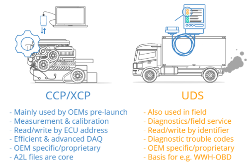
CCP/XCP vs. UDS
Before we deep-dive further on CCP/XCP, it can be useful to understand the role of these communication protocols compared to a slightly similar protocol, Unified Diagnostic Services (UDS).
- CCP/XCP is designed specifically for pre-launch measurement and calibration by OEMs. Typically, CCP/XCP access to ECUs is disabled once vehicles are ready for launch.
- UDS, in contrast, is typically not available in early-stage prototype development and is only added later. It remains available for communication post-launch.
Key Differences:
- Focus:
- CCP/XCP: Primarily for measurement, calibration, and flash programming during development.
- UDS: Focuses on diagnostics and is used by field technicians and OEM-specific scan tools.
- Diagnostics Capabilities:
- CCP/XCP has light-weight diagnostics capabilities.
- UDS is comprehensive and designed for diagnostic purposes.
- Availability:
- CCP/XCP is mainly used pre-launch and disabled post-production.
- UDS is available post-launch and used throughout the vehicle's lifecycle.
Similarities:
- Both protocols support:
- Polling/Cyclic Data Acquisition
- ECU Flashing
- Read/Write Access:
- CCP/XCP: By address
- UDS: By ID
CCP Message Types
To understand how CCP communication works, we will first review the CCP message types.
Overall, CCP communication is done through a request/response logic - similar to what is used in OBD2, UDS, etc. This communication consists of two types of messages:
- Command Receive Object (CRO)
- Data Transmission Object (DTO)
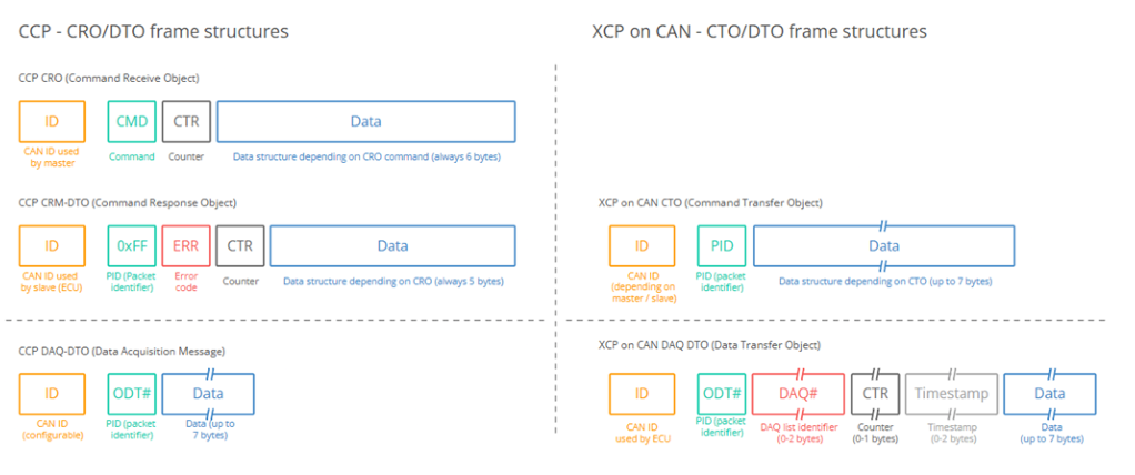
CRO - Command Receive Object
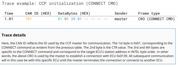
The Command Receive Object (CRO) is a CAN frame sent by the master to an ECU. The 1st byte of the data payload is the command byte (CMD). This controls what command is being issued by the master to the ECU, as per the table overview.
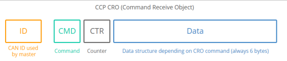
To track the commands issued, the 2nd byte is a counter (CTR). It is incremented by +1 for every command sent by the master and is mirrored in the response from the slave ECU. The remaining 6 bytes depend on the command.
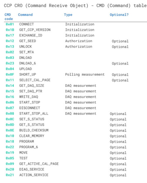
Overview of CRO CMD Values
For a list of CRO commands used in CCP, see the table below:
CCP CAN frame identifiers
In CCP, two CAN identifiers are used: One for messages sent by the master (e.g. 0x701) and one for messages sent by the slave (e.g. 0x702). These identifiers will be specified as part of the A2L (aka ECU Description File), meaning that the master will acquire this information prior to initiating the connection.
Typically low priority IDs are used for CCP to avoid disturbing safety critical info on the bus.
Importantly, this means that the master does not target specific ECUs through various CAN IDs - but rather
through a
connection sequence as shown below.
Example: CCP CRO CONNECT message
Below is an example of a CRO used for initializing communication with a specific ECU:
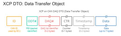
DTO - Data Transmission Object
The Data Transmission Object (DTO) is a CAN frame sent by the ECU to the master. Three types of DTOs exist
as outlined below:
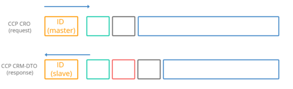
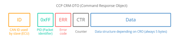
CRM-DTO: Command Response Message
The CRM-DTO is sent by the ECU in response to a CRO from the master. Here, the CAN ID reflects the CAN ID
used by the
ECU (e.g. 0x702).
The structure of the EV-DTO is identical to the CRM-DTO from before, with the EV PID always equal to 0xFE.
Note that the CTR does not have relevance for EV-DTOs.
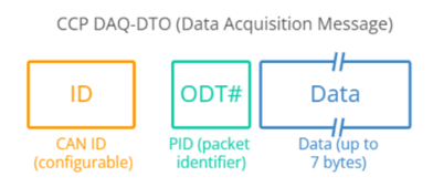
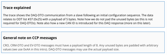
DAQ-DTO: Data Acquisition Message
The DAQ-DTO is used by the ECU to automatically send data to the master in response to a specific event (e.g.
a cyclic counter, a button or similar).
In DAQ communication, the master starts out by 'configuring' the ECU for a specific measurement sequence.
Once initiated, the ECU will output DAQ-DTOs without further CROs from the master.
In the DAQ-DTO the PID is a reference to an 'Object Descriptor Table' (ODT), while up to 7 bytes carry data
related to the ODT. More on this shortly.
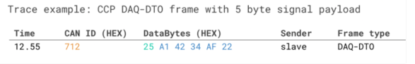
Below is an example of a DAQ-DTO message sent by an ECU to a master:
To recap: A master tool uses CRO messages to send various commands to a slave ECU. The slave ECU can in
turn use DTO messages to respond to the master. Next we'll show how data measurement can be done via
these messages.
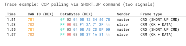
Data acquisition via CCP polling
The simplest solution would be to use a CCP measurement concept called polling.
Below we illustrate how such a communication flow may look:
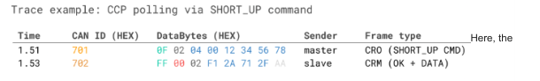
master sends a request to the slave for 0x04 bytes of data stored at the 'source address' 0x12345678. The 4th
byte is 0x00, which reflects the 'address extension' for this ECU source address, which can e.g. reflect a specific
memory segment.
The slave responds with the 4 bytes of data, 0xF12A712F, for this particular source address.
This above flow can be used to e.g. extract real-time parameter data, such as an RPM signal. It's somewhat
similar to how you can request RPM via an OBD2 request/response flow in most cars.
Effectively, 'polling' is simply a sequence of CRO/CRM-DTOs with the master using a command called
SHORT_UP (short upload)
Pros & cons of CCP polling
Polling is simple to set up - simply establish an ECU connection and send the correct request message every X
ms. For many practical use cases this can be a perfectly viable solution.
However, polling has two significant downsides.
1 Polling is inefficient
Polling requires a request message for every response. If you e.g. need to measure a 2-byte signal at 100 Hz,
that increases the busload by 200 frames/second.
The inefficiency is both due to the need for requesting every single response - but also the fact that response
messages are forced to be 8 bytes long, with 3 bytes spent on overhead.
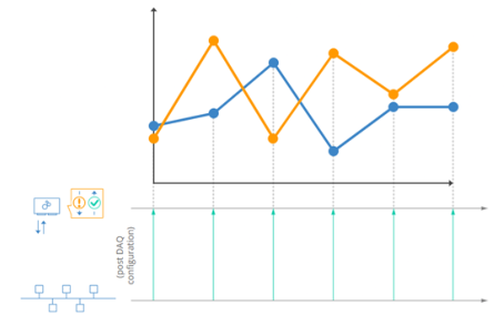
Data acquisition via CCP DAQ
CCP offers an alternative data measurement technique called DAQ (Synchronous Data Acquisition). DAQ is a bit
more complex to initiate, but solves both the downsides of polling.
In simple terms, DAQ works as follows
The master specifies what measurements to record from the slave, as well as what event should trigger the
communication of data. For example, the master could request that signals A and B are broadcast every 10 ms,
while signal C may be broadcast every 100 ms. The master can even configure slaves to broadcast signals
based on events such as a button push or angle change.
Once the DAQ configuration is complete, the master 'starts' the sequence and the slave now autonomously
broadcasts the requested signals using DAQ-DTO messages.
This eliminates the request messages from the master. In addition, the signal data is packaged more efficiently
in the DAQ-DTOs vs. the CRM-DTOs, reducing the busload.
Further, with DAQ it is possible to package related signals in the same DAQ-DTO frames - ensuring that the
requested signals are measured in a time synchronous manner - improving the quality of the data for analysis.
How to configure a DAQ sequence
In order to use the DAQ mode for data measurement, the master has to first configure the ECU accordingly.
In practice, this process is typically handled by sophisticated GUI tools (more on this later). However, to fully
understand what is going on we'll review what happens 'under the hood'.
Two concepts are key in DAQ: Object Descriptor Tables (ODT) and DAQ lists.
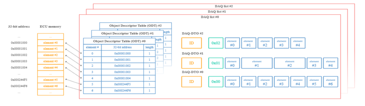
Object Descriptor Table
The Object Descriptor Table (ODT) is a list of references to data elements from the ECU memory.
If we take the 'short upload' example used in CCP polling, the master sends a request specifying three elements:
The data length (in bytes), address extension and source address. With this info, the ECU finds the data and
sends it to the master.
The concept of an ODT is similar:
An ODT is simply a list of element references. Each entry in the ODT reflects an ECU source address - and
optionally also an address extension and data length. In other words, an ODT entry contains the same info that
we used to poll a signal
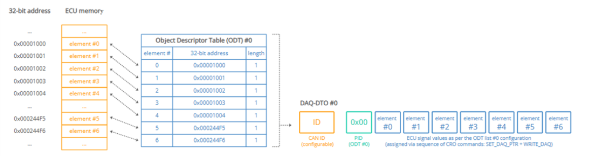
DAQ lists
When working with multiple ODT lists, it's useful to group them together. These groups of ODT lists are referred
to as DAQ lists. For example DAQ list #0 may contain ODT #0, ODT #1 and ODT #2.
A DAQ list is characterized by the way in which the data is sampled:
DAQ list #0 may be set up so that all DAQ-DTOs within it are sampled every 10 ms
DAQ list #1 might be configured so that DAQ-DTOs in it are sampled when a button is pressed
...
In other words, a separate DAQ list is required for each unique sampling logic requested for the data
measurement.
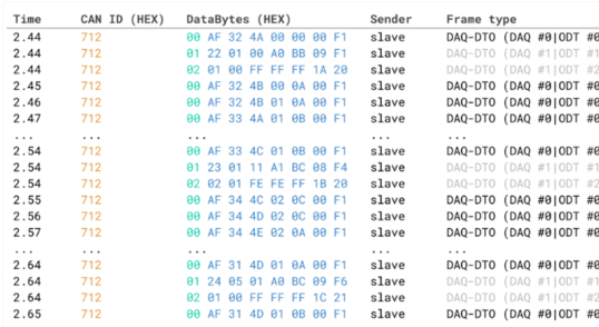
We will describe the DAQ and ODT initialization shortly, but first consider below example trace for an already
initiated DAQ sequence:
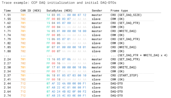
How to initialize a DAQ sequence
We've now looked at both the ODT and DAQ lists - but how do we define these over CAN?
In simple terms, the configuration of DAQ lists is done through a (potentially long) sequence of CRO/CRM-DTO
frames. Here, the master essentially specifies the entire DAQ/ODT/element structure element-by-element. To
define a new signal (aka element), the master specifies the address, length and address extension. Next, the
master informs the ECU how to package the element in DAQ-DTOs by linking the element to an ODT#
and DAQ#
To understand this in detail, see below trace example and subsequent explanation:
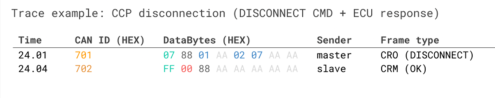
How to disconnect from an ECU
Once the data acquisition has completed, the master may disconnect from the ECU via the DISCONNECT
command.
Let's look at an example trace:
Decoding CCP signal data from ECUs
In CCP polling/DAQ, you are in practice recording raw CAN frames with specific signal encoding structures.
In order to make sense of the recorded data, you need to decode it to human-readable form aka physical values.
This is the same concept as we've explained in several other CAN-related intros, incl. our intro to CAN
bus, J1939, OBD2 and DBC files.
However, CCP decoding involves some extra complexities that we will explain below.
Decoding CCP polling data
Let's review an extended version of the CCP polling request/response from before:
This reflects a decoding challenge: The ECU sends different signals with the same CAN ID - with no way to
identify them in the payload.
In simplistic terms, we can solve this by "repackaging" the payloads as follows:
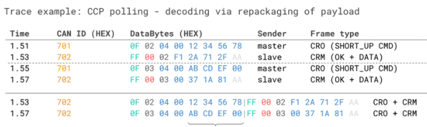
By doing so, we can process this using multiplexing logic - similar to how we handle OBD2
and UDS decoding. Here, the CAN ID to look up is 0x702 and the multiplexor is found in the 5th to 8th byte, while the
signal value is found in the 12th to 15th byte. Two separate decoding rules can now be specified, with the
relevant one dependent on the value of the 4-byte multiplexor.
In practice such a reconstruction of CAN frames can be done in e.g. a Python script,
assuming the CAN trace includes both the request and response data. Once the CAN frames are reconstructed, it is possible to use DBC
files for decoding the data via multiplexing. Alternatively, the data can be loaded into a software tool
supporting CCP/XCP decoding directly.
Decoding CCP DAQ data
Let's briefly review a snippet of the post-initialization DAQ trace from before:
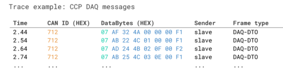
As evident, the DAQ-DTO messages have a pre-specified CAN identifier (0x712 above) and a payload in which
the 1st byte equals the ODT list identifier aka ODT PID (0x07 above). As a result, it is not necessary to
"combine" the DAQ-DTO response frames to uniquely identify which frames contain which signals - this can
directly be identified through a combination of the CAN ID and the ODT PID.
This fact makes the decoding of DAQ-DTO messages simpler than the polling messages. In fact, you can
directly create a DBC file with multiplexing as long as you know the signal encoding in the remaining bytes of
each ODT list.
The above should make it clear that CCP polling/DAQ can be treated within the normal logic of CAN bus frame
decoding - though both involve some tweaks. DBC files can be used to process the data - but this format is not
the most common choice for working with CCP data. Below we explore another file format that is generally used, the A2L or ASAP2 format.
XCP on CAN - the basics
We have now gone through the basics of CCP. Next, we'll consider XCP on CAN with focus on frame structures.
The XCP packet
To understand the structural changes in XCP on CAN vs. CCP, consider below comparison of the CCP
CRO/DTO and the XCP CTO/DTO. As evident, XCP packets include the XCP CTO (with a similar role as the
CCP CRO and CRM-DTO) and the XCP DTO (with the XCP DAQ-DTO playing a similar role as the CCP DAQ-DTO).
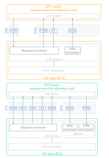
We will cover the XCP on CAN message types in more detail below.
XCP CTO - Command Transfer Object
In XCP on CAN, the CTO is a CAN frame for transferring control commands, incl. commands (CMD), command
responses (RES), errors (ERR), events (EV) and service requests (SERV).
In contrast to the CRO in CCP, the CTO is used by both the master and ECU. Note also that a CMD packet from
the master must be answered with a RES or ERR packet from the ECU, while the other packet types are sent
asynchronously.
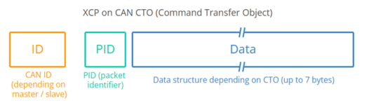
If we look at the CTO payload, the 1st byte reflects a Packet Identifier (PID). The remaining 7 bytes in an XCP
on CAN CTO payload consists of data, specific to the type of CTO packet.
If we compare this structure to the CRO of CCP, it's similar, except for the exclusion of the command counter
byte in XCP.
CAN bus identifiers in XCP
XCP communication requires at least two CAN bus identifiers: One for the master (e.g. 0x551) and one for the
ECU (e.g. 0x552). If the master needs to communicate via XCP with more than one ECU, an additional set of
identifiers will be required.
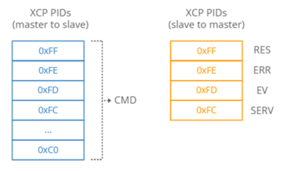
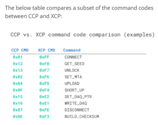
The actual values of the CMD byte across XCP and CCP differ as well. For example, CCP uses 0x01 for the
CONNECT command, while XCP uses 0xFF. See also the table overview for the assignment of CTO PIDs
depending on whether messages are sent from the master or slave.
See also below comparison of CCP vs. XCP CMD codes:
Example: XCP CTO CONNECT message
As in CCP, let's look at how a CONNECT sequence may look in XCP on CAN:
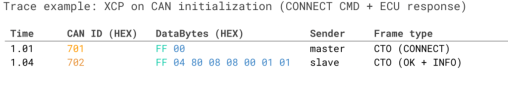
Note that the example does not use the 0xAA padding, as this is optional in XCP on CAN.
In the trace, the master sends a CONNECT CMD (0xFF) to the ECU with the communication mode set to normal
(0x00). Note that, in contrast to CCP, the master does not need to specify a station address in the payload of the
CONNECT frame. This is because the CAN identifiers already uniquely identify which ECU the master is
communicating with.
The ECU responds with a CAN frame in which the 1st byte equals the positive response PID (RES). The 2nd
byte is the resource availability, similar to the seed & key CCP communication with 0x04 e.g. meaning that DAQ
is available. The 3rd byte relates to the 'communication mode' (here 'optional'), while the 4th byte is the
maximum CTO size (here 8 bytes). The 5th and 6th byte equal the maximum DTO size (here 8 bytes), while the
7th and 8th bytes equal the XCP protocol layer version and transport layer version respectively (both 1 in this
case).
Example: XCP Polling
With a connection established, the master can e.g. initiate polling. As in CCP, this can be done via a
SHORT_UPLOAD command:
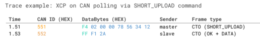
here, the master sends a SHORT_UPLOAD CMD (PID 0xF4) for 2 bytes of data. The 3rd byte is reserved, while
the 4th byte of the CTO is the address extension (in this case 0). The remaining 4 bytes equal the source
address 0x12345678 (INTEL byte order).
In response to the command CTO, the ECU sends a response CTO with the value of the 2 bytes of
The XCP DTO is used for sending synchronous data. In particular, the DTO is used in DAQ measurement
(similar to the role of the DAQ-DTO in CCP). In XCP, it also enables the transfer of 'stimulation' (STIM) data that
can be used in bypassing the normal algorithm within an ECU. Stimulation and bypassing are topics that we will
not cover here.
We will also not go into detail on the XCP DAQ measurement as it's similar in concept to CCP.
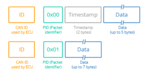
The XCP DTO timestamp
The XCP DTO timestamp is optional and is implemented as an incrementing counter, with the incrementation
logic specified in the A2L file. If a timestamp is to be included for a specific DAQ list, it will be written into the 1st
ODT list (but not subsequent ones if more ODT lists exist within the same DAQ list).
Application Of The XCP Protocol:
- It is used in ECU development.
- It is used in systems for function and environmental tests of ECUs.
- It is used in a test bench for combustion engines, gearbox, climate control, instrument cluster calibration,
or wheel alignment, etc. - It is used for measurements and calibration in pre-production vehicles.
- It is also used in a general CAN application outside the vehicle industry.
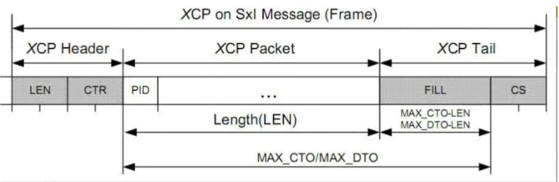
XCP Protocol Frame Format:
An XCP message consists of three parts: Header, Packet, and Tail. The Header and the Tail are part of the
Transport layer and consist of a Control Field, the content of which depends on what bus is used. The Packet part of
an XCP protocol message consists of an Identification Field, Timestamp Field (optional), and a Data Field, and is
a generic part of the protocol layer.
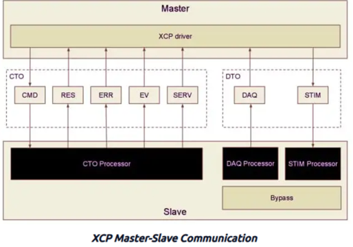
XCP Packet:
In the XCP protocol, two different types of packets are used in the communication via XCP, Command Transfer
Object (CTO), and Data Transfer Object (DTO). The CTO has five types of objects:
- CMD (Command).
- RES (Response).
- ERR (Error).
- EV (Event).
- SERV (Service Request Processor).
The DTO has two types of objects that are both used for event-driven reading of variables from, or writing values
to, the memory of the slave.
- DAQ (Data Acquisition).
- STIM (Stimulation).
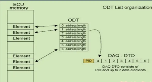
Data Acquisition (DAQ):
A core feature of the XCP protocol is the DAQ lists. In order to be able to send a large
amount of data in a small amount of time and with low bandwidth load desirable, XCP offers the ability to
configure lists that take care of transmitting requested data at a given interval. Each DAQ list (Figure 10) has
a number of Object Descriptor Tables (ODTs) that in turn contain Object Descriptor Table Entries (ODT Entries)
as described in Figure 11. Each ODT Entry has an address and a length, these make out the description of
the parameter that it represents. When the DAQ list has processed, the contents of the list are copied to the
corresponding address of each entry in each ODT. The slave doesn’t receive an acknowledgment that the
master has received the data correctly.
For each DAQ-list configuration, a number of ODTs are defined, each having a unique identifying PID.
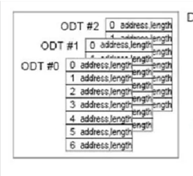
Each ODT entry in a DAQ list points to a memory element with specified address and length
XCP ODT Diagram
DAQ-list Configuration:
The XCP protocol has two different ways of configuring the DAQ-lists, static, and dynamic. While static configuration is mandatory according to the specification, dynamic configuration seems to be the preferred way (as an example CANape only uses the dynamic configuration in their examples).
Which configuration method that is to be used is decided exclusively by the slave, there is no way for the master to request one or the other, nor can both be used in parallel. In addition to the configurable DAQ-list (static or dynamic), the slave can also have a number of predefined DAQ-lists. These lists cannot be altered in any way. Each ODT entry has a predefined address and size. The only thing the master is allowed to do is configure their direction, prescaler, priority, and which event channel it should be connected to.
Static Configuration:
In the static configuration of the XCP protocol, the slave already has a structure of DAQ-lists with ODTs, and the ODTs have entries. This configuration cannot be edited. If there is only one DAQ-list, that has three ODTs and the ODTs have 5 entries each, then this is all the master has got at its disposal. The entries can be edited, i.e., the address and address extension that maps it to the memory space can be changed. A lot of the DAQ-list's properties can also be changed, just as in the case with the predefined list.
Dynamic Configuration:
The dynamic configuration is, as the name suggests, less restricted. The XCP protocol master can request allocation of any number of the DAQ-lists, each DAQ-list can have any number of ODTs, and the ODTs can have any number of entries. There are some restrictions to the command sequence of the allocation, see Figure 12 and the following list:
- The allocation must always start with sending a command to clear the previous allocations; this is done with the
FREE_DAQ. This will reduce the number of DAQ-lists to the predefined lists if any exists on the device. - The next step is to allocate the DAQ-lists; this can either be done one at a time or by allocating all the lists at once. If a
FREE_DAQhas not been executed before this step, the device will return an error message. - After allocating the DAQ-lists, the master can start allocating ODTs to the different lists. All the ODTs in all the DAQ-lists need to be allocated before the first entry is allocated.
- Finally, the entries are allocated as:
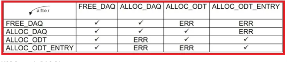
XCP Dynamic DAQ Diagram
The parameter MAX_ODT is defined in the AUTOSAR specification as the maximum number of ODTs available on the slave, though its range suggests that it is instead the maximum number of ODTs available in the DAQ-list. More about the different XCP protocol parameters can be found in the XCP AUTOSAR module.
STIM Lists – Data Stimulation Lists
The opposite of DAQ lists are STIM lists. They provide a means for the master to write to (stimulate) the slave in a controlled manner. When the master writes to a STIM list, the data is buffered in the slave until the STIM list is executed, at which point the simulation data is copied to specified memory addresses of the ECU.
STIM lists execute at certain intervals or at specific points in the program running on the ECU. This avoids the problems of directly modifying control parameters mid-execution of some control-loops. Instead, it allows the ECU to apply new parameters at controlled points in time.
The STIM lists are built up in the same fashion as DAQ lists. They consist of ODTs (Object Data Descriptors) and ODT entries. Each ODT is transmitted in a single STIM packet from the master to the slave and consists of multiple ODT elements. Each element has previously been configured to point to a memory address + extension with a specified length.
Processing Event Channel
Each DAQ-list is connected to an event channel that dictates how often the DAQ-list should be executed. The DAQ-list also has a parameter called a Prescaler that states how many event channel executions should occur between each time the DAQ-list is run. If this parameter is set to 1, the DAQ-list will be run each time the event channel is executed.
XCP Signal Bypassing
Bypassing is a feature of the XCP that allows replacing some part of an ECU’s control logic with code that resides on the XCP master. For example, one could replace part of a calculation in the ECU with code that executes in Matlab/Simulink on the master to test out new controller methods without the need to reprogram the ECU. It combines the use of DAQ lists with STIM lists to achieve this.
The use of this feature requires additional instrumentation of the ECU’s code. When bypassing is activated on some part of the ECU’s program, the ECU will send a DAQ packet as it enters the bypassed code, with the parameters required to calculate a response to the master. The slave then enters a waiting state. When the master receives the DAQ list for the bypassed code, it replies with a STIM packet containing the result of the calculation. At this point, the ECU resumes operation with the received STIM data as the result of the bypassed code.
XCP-Security Access
The XCP protocol provides an ECU unlock feature similar to the UDS protocol. To ensure that access to the ECU is restricted to authorized persons, a security mechanism called Seed & Key is a part of the XCP specification. A slave unique key is needed to grant access to a slave, and the master must ask the slave for a seed to compute the key and gain access. The algorithm to calculate the key is unknown to the master to ensure confidentiality. The key algorithm is encapsulated in a file called SeedNKey.DLL, which the master uses to calculate the key with the help of the seed provided by the slave.
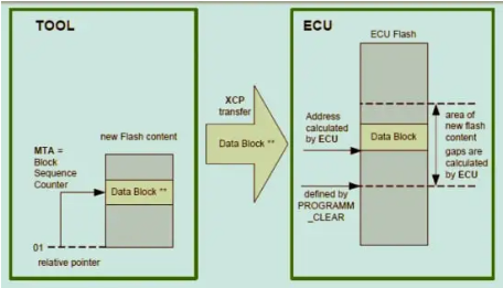
XCP-ECU Flash Programming
In the XCP object called SECTORS, the physical layout of the ECU memory is described. The start addresses and sizes of the SECTOR are important when reprogramming the ECU.
Programming of flash memory in a slave device can be divided into three parts:
- Administration before programming: For example, checking what version of the software is currently loaded in the memory.
- The flash process: This is when the memory is programmed.
- Administration below: For example, performing checksum control to see if the flashing process was successful.
The XCP protocol standard does not support special commands for version control because the administration steps are project-specific and depend on the ECU. However, the ECU functional description can specify which standard XCP commands can be used for the administration actions like version control.
The XCP standard offers seven commands to be used especially for programming:
PROGRAM_STARTPROGRAM_CLEARPROGRAM_FORMATPROGRAMPROGRAM_VERIFYPROGRAM_RESET
XCP-Flash Memory Access
There are two different flash access methods supported by the XCP protocol to be used in the flash process: Absolute Access Mode and Functional Access Mode, which both use the same commands but with different parameters.
Absolute Access Mode:
This is the default mode and is used when the physical layout of the flash memory is well known to the programming tool. The flash content to be programmed must be available, and the address information of the data must be known. The physical layout information can be read out of the ECU or in the description file, depending on how it is done in the project. The block of data in the Command Transfer Object (CTO) will be programmed into the flash memory starting at the Memory Transfer Address (MTA), which will be incremented by the number of bytes of data being programmed into the memory.Access by Address:
This is an alternative mode that uses similar methods but may involve different handling of address or memory layouts.
Main Branch
- Simtestlab Sweden AB
- Org.nr: 559386-6055
- VAT Number: SE559386605501
- SWEDEN (HQ) - Sprintergången 7
- support@simtestlab.se
- +46 76 976 82 63
- Copyright 2022. All Rights Reserved.