- XCP Protocol Implementation in XMC4800 Controller
XCP Implementation with TS Master and XMC Controller
Giri velavan
Published: 8 months ago
XCP Protocol Implementation in XMC4800 Controller
Basics of XCP Protocol
1. Introduction to XCP
The Universal Measurement and Calibration Protocol (XCP) is a standardized communication protocol used for real-time data acquisition, calibration, and flashing of electronic control units (ECUs). It was developed by ASAM (Association for Standardization of Automation and Measuring Systems) and is widely used in automotive and embedded systems for testing and development purposes.
2. Features and Benefits
- Real-time Data Acquisition: XCP allows high-speed measurement and calibration of parameters within an ECU without significantly impacting system performance.
- Transport Layer Independence: It can operate over various transport layers, including CAN, Ethernet, SPI, and USB.
- Scalability and Flexibility: XCP supports a wide range of applications, from simple calibration tasks to complex testing environments.
- Event-Triggered Data Logging: The protocol can be configured to collect and transmit data based on specific triggers or conditions.
3. Communication Mechanism
XCP operates on a master-slave architecture, where:
- The Master (typically a PC-based tool) sends commands and requests data.
- The Slave (ECU or embedded system) responds with the requested information.
The protocol uses a packet-based communication system, including commands for read/write operations, calibration, flashing, and event-based measurement. Communication is managed through a standardized Application Programming Interface (API), ensuring compatibility across different vendors.
4. Applications in Automotive and Embedded Systems
- ECU Calibration: Used extensively in the automotive industry for tuning engine control parameters in real time.
- Data Logging and Debugging: Enables engineers to analyze system behavior under different conditions.
- Software Flashing: Supports firmware updates and reprogramming of ECUs.
- HIL and SIL Testing: Plays a crucial role in hardware-in-the-loop (HIL) and software-in-the-loop (SIL) simulations for validating system performance before deployment.
XCP continues to be a vital tool in modern automotive development, ensuring efficient testing, calibration, and data acquisition in embedded systems.
XCP Over CAN Protocol
Here is a structured list of the software and hardware used for XCP calibration via CAN communication:
Software Used:
- TS Master – Used for calibration of parameters and sending XCP commands over CAN.
- DAVE IDE – Used for processing commands received from TS Master and executing necessary code on the XMC4800.
Hardware Used:
- XMC4800 IoT Connectivity Kit – Used for replying with CAN frames based on received XCP commands.
- Kvaser CAN Hardware – Used for sending and receiving CAN frames between TS Master and the XMC4800 controller.
Implementation Steps
Step 1: Download and Install DAVE IDE
.png)
Select the right version for your system and install it.
Step 2: Create a New Project in DAVE IDE
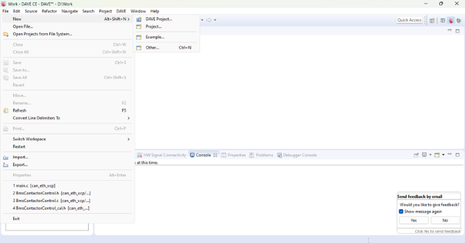
- Open DAVE IDE → Go to File → Select DAVE Project
Step 3: Name and Select Project Type
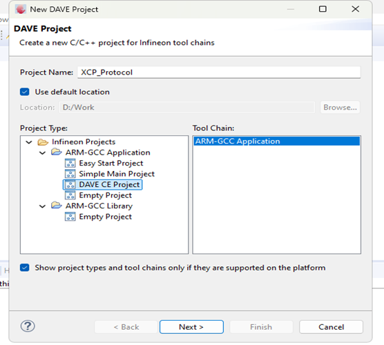
- Name the project → Select DAVE CE Project → Click Next
Step 4: Select Your Controller
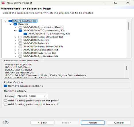
- Choose XMC4800 IoT Connectivity Kit → Click Finish
Step 5: Add CAN_NODE to the Project
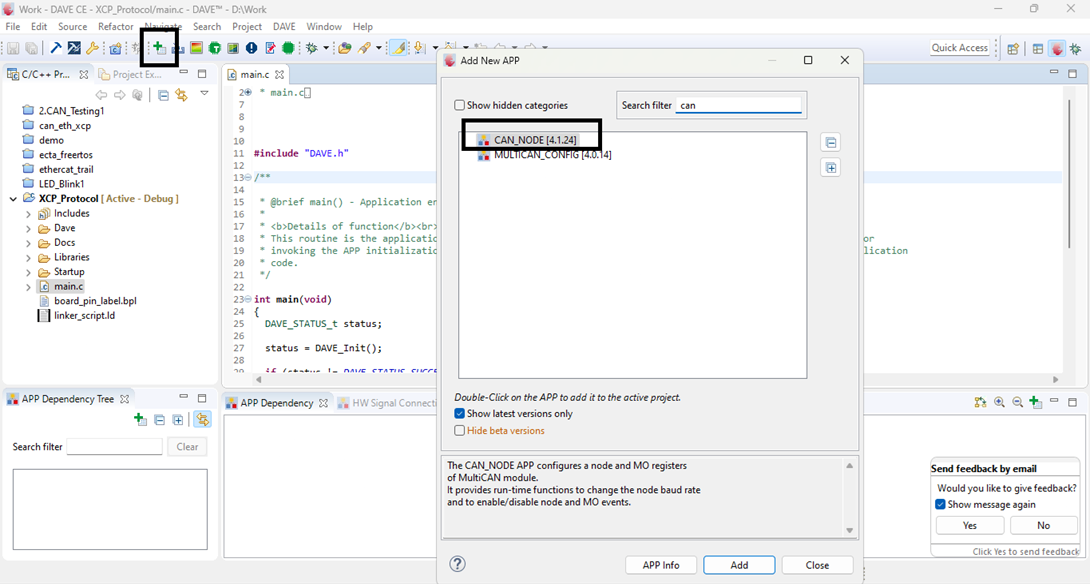
- Click on App Dependency → Search for CAN → Add CAN_NODE
Step 6: Configure CAN_NODE
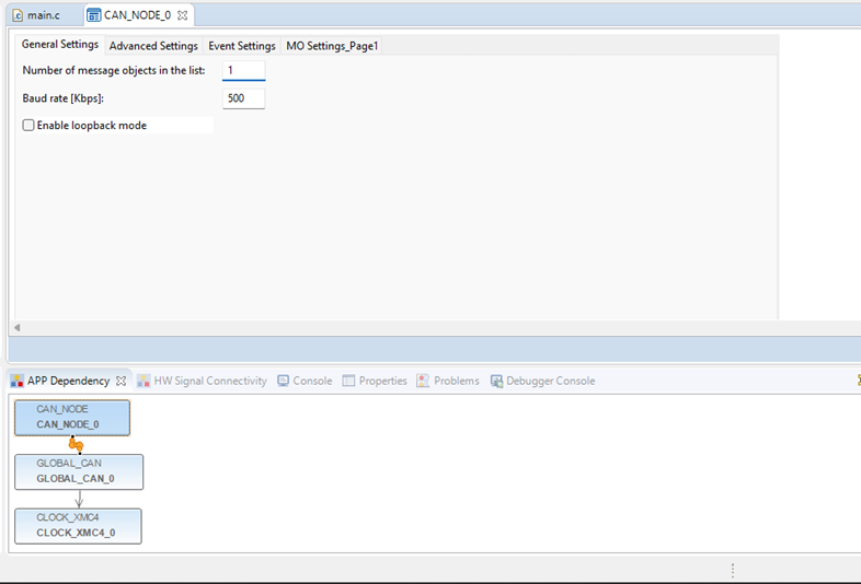
- Click on CAN_NODE_0 App Dependency → Input the Number of Message Objects (e.g., 1) → Set Baud Rate (e.g., 500 Kbps)
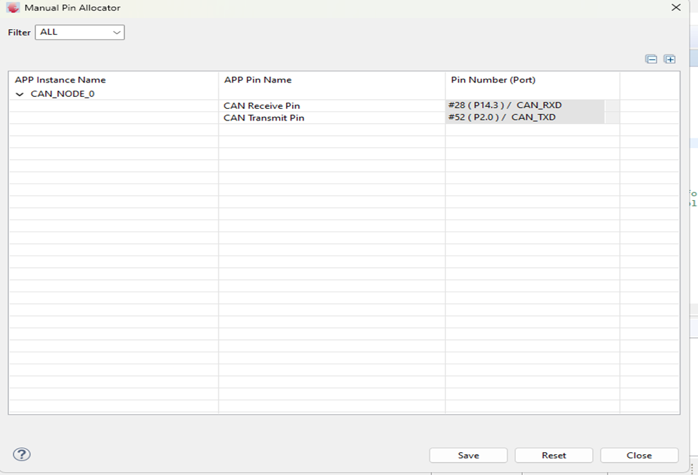
Step 7: Configure Pin Allocator
- Click on Manual Pin Allocator → Select Pins → Save
Step 8: Select the Pins and Save it
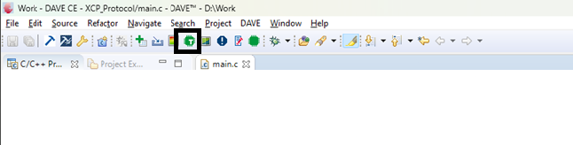
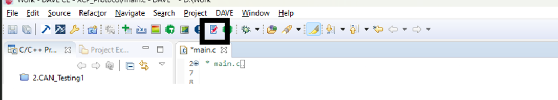
- Click on the Generate Code icon
Step 9: Now Click on the Generate code icon
Step 10: Download XCP Stack
- Search for XCP inside the repository
- Use the Include Header Files and Source Codes from
Core -> Communication -> XCP
Step – 11
Installation of TS Master tool for Measurement
Software Downloading Repo Link from Official TS Master Repo
-> https://github.com/TOSUN-Shanghai/TSMaster.git
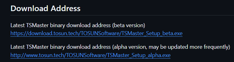
- The Above is the two software Extensions and install based on your System Configurations.
- Install the Software.
Step – 12
After Installing TS Master tool then Follow the Below Steps
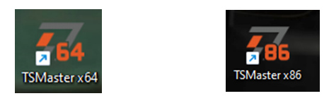
- There will be Two Icons added to your System after the installation of the TS Master tool.
- Select the Appropriate Icon and Folloe the below Steps.
Step – 13
- Click on the Create New Project
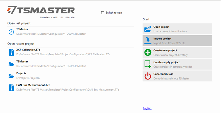
2. Click on the Calibration
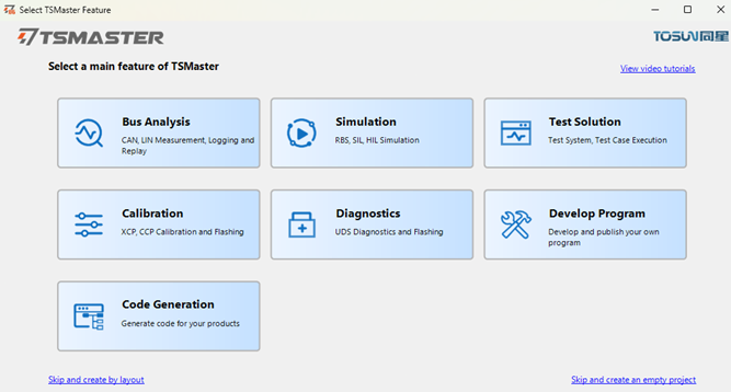
- Now select on the XCP Calibration
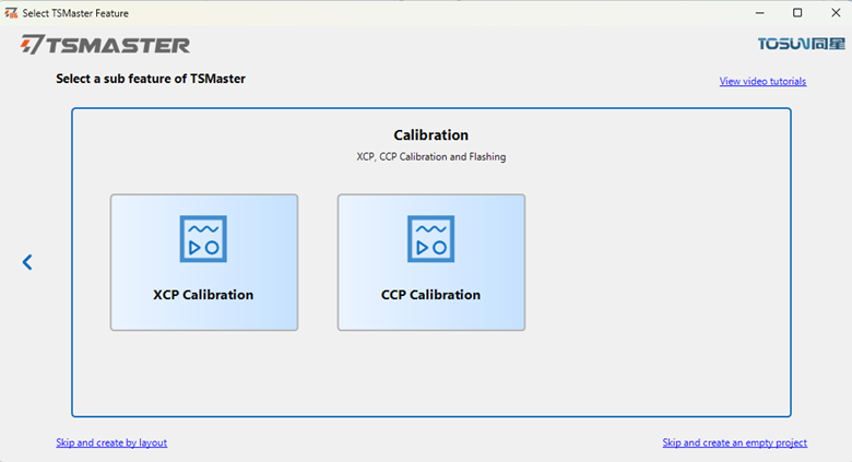
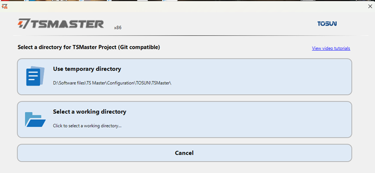
- Select the Directory you need to store the Projects
Step – 14
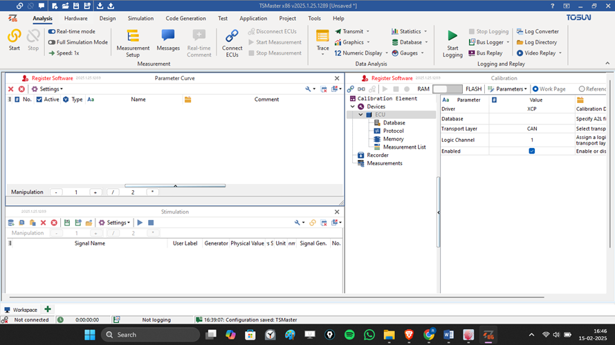
The Below steps will be for the TS Master toon Configurations
The Interface will be Looks Like this
- Click the Channel Selection
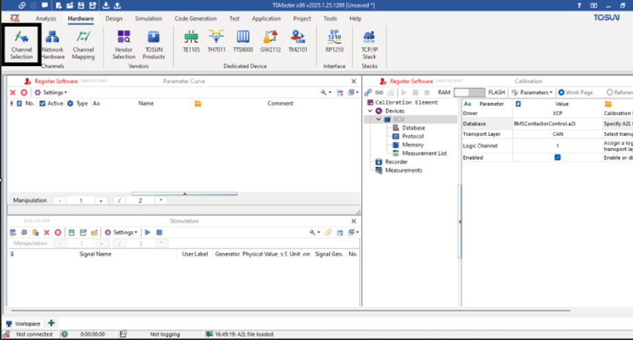
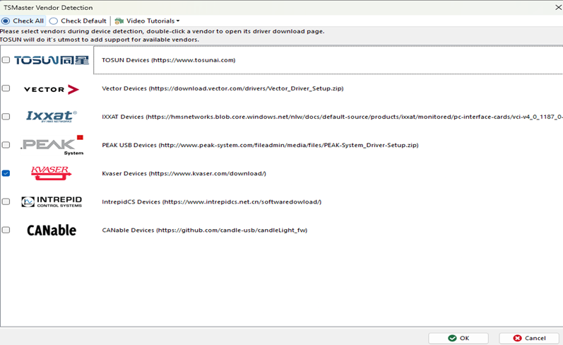
2. After Going to the Channel Selection click on the Vendor Selection
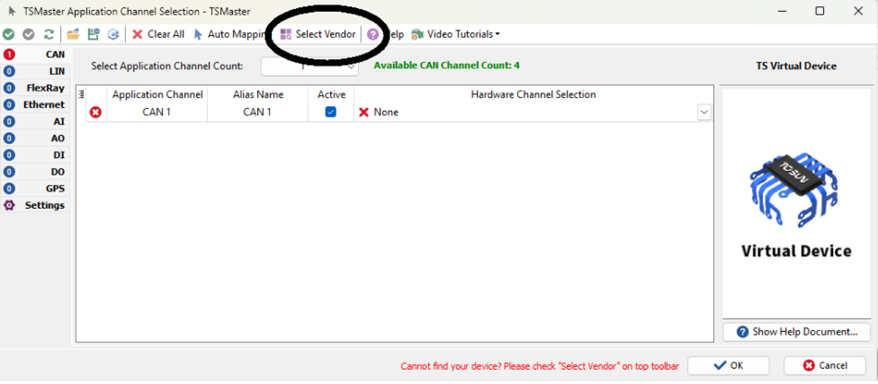
3. Now select your Appropriate Hardware Vendor (Mine is Kvaser) and click ok
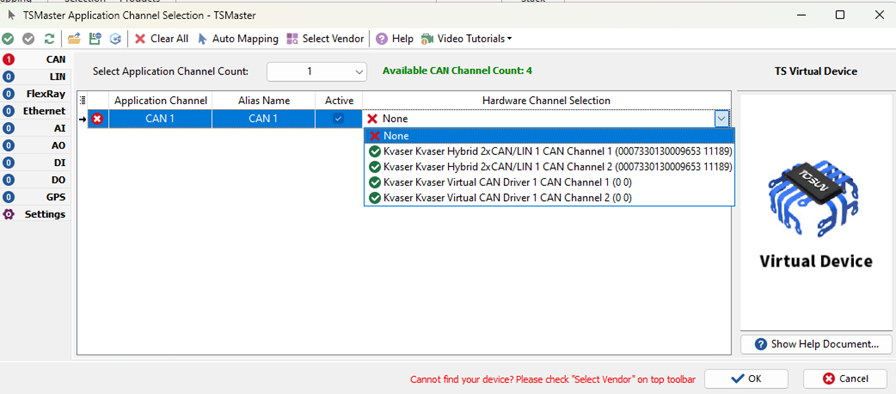
- Select your Hardware connected Channel Port and click ok
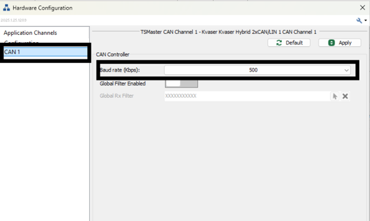
- Again click on the Hardware and go to the Network Hardware
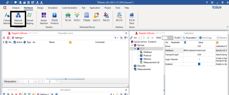
- On the Network Hardware page select the CAN 1 and set the Baud rate (The Slave Controllers baud rate and the Master TS Master’s Baud rate should be same).
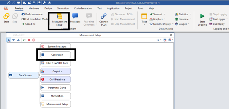
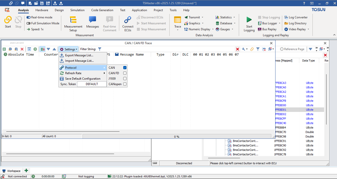
- Click on the Measurement Setup Icon then the page will be Look like the Below and then select Calibration.
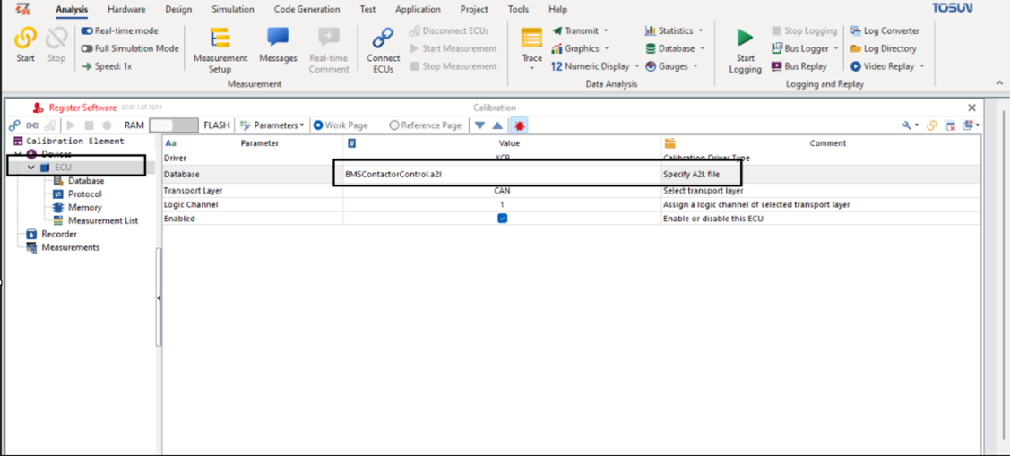
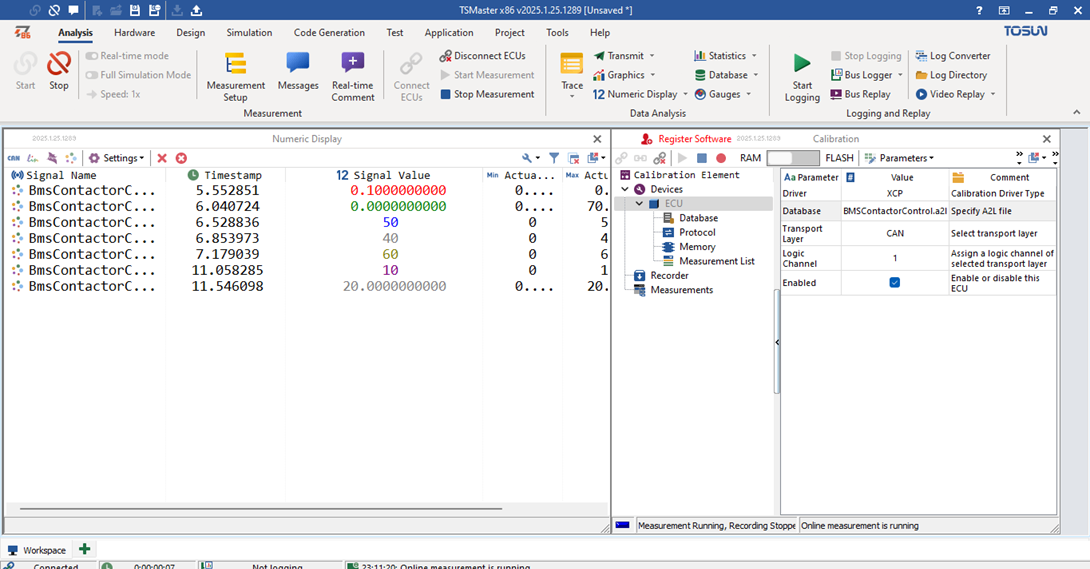
- After selecting the Calibration page go to the ECU and then Specify the A2L File for your Project. The A2L variable’s and the ECU variables Address should be same.
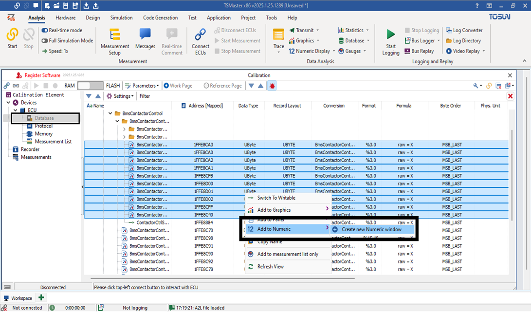
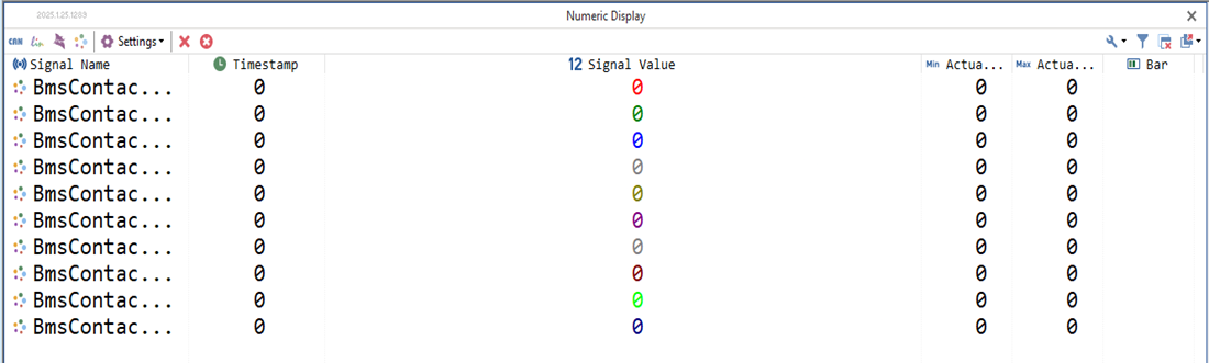
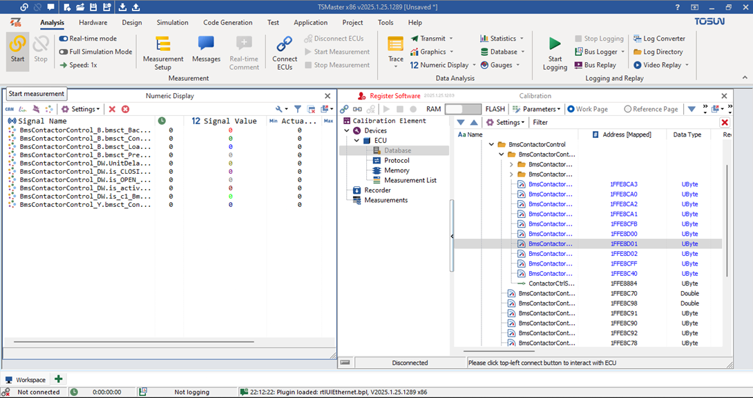
- And then in the Database select the variables that needs to be measured and then finally Select the Option Add to Numeric and Create new Numeric window.
- The Display will be opened or you can open this page using the Measurement setup Icon.
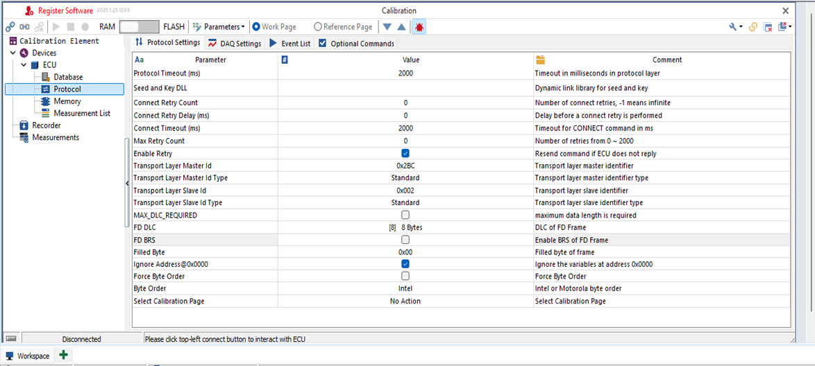
11. Then, in the ECU, go to the Protocol section. On the Protocol page, set the Transport Layer Master ID. You can assign any value (mine is 0x2BC = 700), but ensure that the same value is used in the ECU’s receiving condition. The Receiving ID from the Slave ECU is 2 (in decimal)
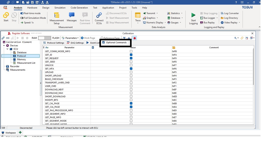
- On the same Protocol page go to the Optional Commands Section. Then select the DAQ related and MTA Commands and also the commands based on your commands select the Commands.
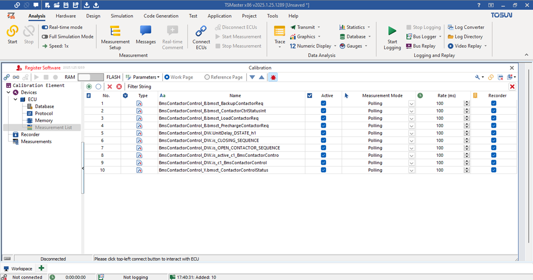
13.On the ECU, go to the Measurement List. There, you will find the list of measurement variables you have selected. Then, select the refresh rate required to fetch the value changes in the variables from the ECU.
- Now go to the Trace icon on the Top and Ensure that you have selected your right CAN version
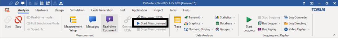
15. Start the Measurement by Clicking the Icon
- Then check the system message console
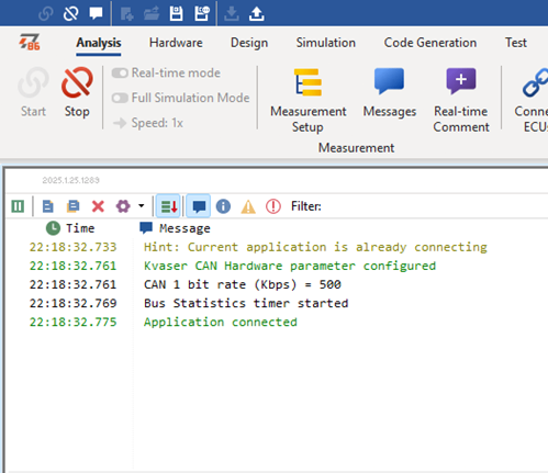
- The Application Connected message will be Shown if it is Rightly connected
17.Connect to the ECU using the Connect icon
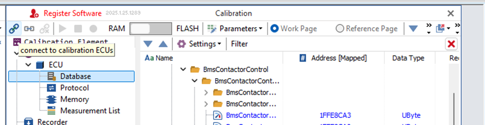
- Then Click on the Start Measurement
19. Then The measurement of Variables will be started
Commands and Responses
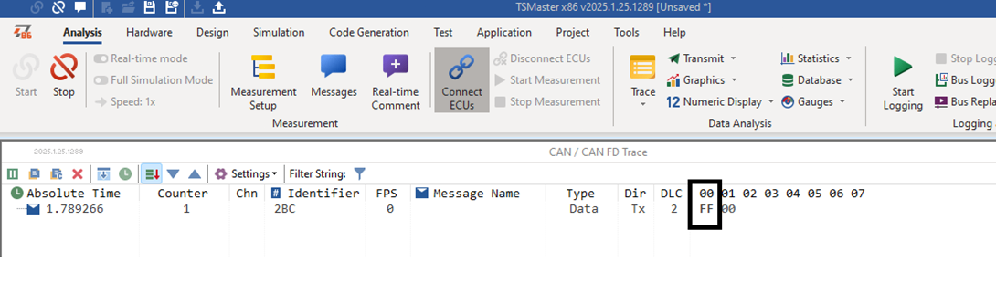
- The Above command FF Represents the Connection Request command from the TS Master to the Slave Controller.
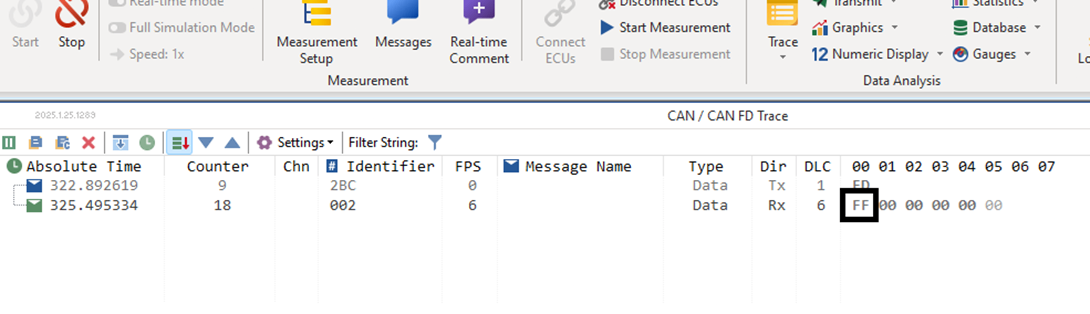
- Like Above If the Slave gives back the FF command as response then it indicates that the Ts Master tool is connected with the slave controller.
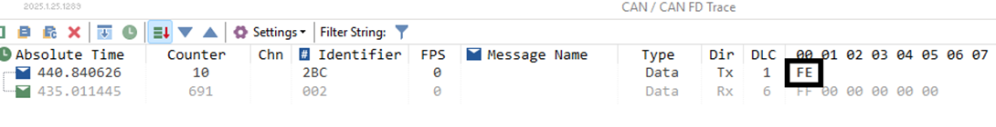
- The FE Command represents the Disconnect command sent from the TS Master, meaning it stops communicating with the Slave Controller.
Below are the Commands for XCP Protocol
Standard Commands
| Command | PID |
|---|---|
| CONNECT | 0xFF |
| DISCONNECT | 0xFE |
| GET_STATUS | 0xFD |
| SYNCH | 0xFC |
| GET_COMM_MODE_INFO | 0xFB |
| GET_ID | 0xFA |
| SET_REQUEST | 0xF9 |
| GET_SEED | 0xF8 |
| UNLOCK | 0xF7 |
| SET_MTA | 0xF6 |
| UPLOAD | 0xF5 |
| SHORT_UPLOAD | 0xF4 |
| BUILD_CHECKSUM | 0xF3 |
| TRANSPORT_LAYER_CMD | 0xF2 |
| USER_CMD | 0xF1 |
Calibration Commands
| Command | PID |
|---|---|
| DOWNLOAD | 0xF0 |
| DOWNLOAD_NEXT | 0xEF |
| DOWNLOAD_MAX | 0xEE |
| SHORT_DOWNLOAD | 0xED |
| MODIFY_BITS | 0xEC |
Standard Calibration Commands
| Command | PID |
|---|---|
| SET_CAL_PAGE | 0xEB |
| GET_CAL_PAGE | 0xEA |
| GET_PAG_PROCESSOR_INFO | 0xE9 |
| GET_SEGMENT_INFO | 0xE8 |
| GET_PAGE_INFO | 0xE7 |
| SET_SEGMENT_MODE | 0xE6 |
| GET_SEGMENT_MODE | 0xE5 |
| COPY_CAL_PAGE | 0xE4 |
Periodic Data Exchange – Basics
| Command | PID |
|---|---|
| SET_DAQ_PTR | 0xE2 |
| WRITE_DAQ | 0xE1 |
| SET_DAQ_LIST_MODE | 0xE0 |
| START_STOP_DAQ_LIST | 0xDE |
| START_STOP_SYNCH | 0xDD |
| WRITE_DAQ_MULTIPLE | 0xC7 |
| READ_DAQ | 0xDB |
| GET_DAQ_CLOCK | 0xDC |
| GET_DAQ_PROCESSOR_INFO | 0xDA |
| GET_DAQ_RESOLUTION_INFO | 0xD9 |
| GET_DAQ_LIST_INFO | 0xD8 |
| GET_DAQ_EVENT_INFO | 0xD7 |
Periodic Data Exchange – Static Configuration
| Command | PID |
|---|---|
| CLEAR_DAQ_LIST | 0xE3 |
| GET_DAQ_LIST_INFO | 0xD8 |
Periodic Data Exchange – Dynamic Configuration
| Command | PID |
|---|---|
| FREE_DAQ | 0xD6 |
| ALLOC_DAQ | 0xD5 |
| ALLOC_ODT | 0xD4 |
| ALLOC_ODT_ENTRY | 0xD3 |
Flash Programming Commands
| Command | PID |
|---|---|
| PROGRAM_START | 0xD2 |
| PROGRAM_CLEAR | 0xD1 |
| PROGRAM | 0xD0 |
| PROGRAM_RESET | 0xCF |
| GET_PGM_PROCESSOR_INFO | 0xCE |
| GET_SECTOR_INFO | 0xCD |
| PROGRAM_PREPARE | 0xCC |
| PROGRAM_FORMAT | 0xCB |
| PROGRAM_NEXT | 0xCA |
| PROGRAM_MAX | 0xC9 |
| PROGRAM_VERIFY | 0xC8 |
Main Branch
- Simtestlab Sweden AB
- Org.nr: 559386-6055
- VAT Number: SE559386605501
- SWEDEN (HQ) - Sprintergången 7
- support@simtestlab.se
- +46 76 976 82 63
- Copyright 2022. All Rights Reserved.